


Design and Practical Implementation of a Simple Multimeter
A comprehensive project assignment for the Crystal Clear Electronics 1 curriculum
The instructor of our partner institution, Bolyai Farkas Theoretical High School from Marosvásárhely, József Domokos, further developed the 2024 “Crystal-Clear Electronics” summer camp project together with his high school students. Within the framework of an extracurricular activity, the team extended the assignment by designing a printed circuit board. They prepared a project documentation, which is presented below. Aside from the optional bonus task, the knowledge provided by the Crystal Clear Electronics 1 (CCE1) curriculum is sufficient to complete this project.
On the following link the project files can be downloaded: Download
Chapters which are needed for this project
The following chapters from the CCE1 curriculum must be thoroughly understood to successfully complete the project:
- 03 Electronic Symbols
- 05 Multimeter, Ohm’s Law in Practice
- 06 Linear Power Supplies and Diodes
- 09 Microcontrollers I.
- 10 IT Basics
- 11 Microcontrollers II.
- 12 Debugging - Troubleshooting in the Program
- 18 USB Communication
- 22 Processing Analog Signals, the ADC
The 2024 CCE 1 summer camp project
The aim of this project is to provide practical experience with the microcontroller-related chapters of the CCE1 curriculum and to apply this knowledge in a comprehensive project. The project is to design and implementat a simple multimeter. The device can measure the voltage across a potentiometer and the current flowing through two parallel-connected LEDs. The multimeter is designed to measure both voltage and current.
The requirements are as follows: voltage measurements must cover the 0–5 V range and current measurements must cover the 0–50 mA range.
Current measurement is actually based on voltage measurement, utilizing the knowledge from Chapter 5 (Multimeter, Ohm’s Law in Practice). Voltage is measured using the ADC built into the ATMega16A microcontroller, as described both theoretically and practically in Chapter 22 (Processing Analog Signals, ADC).
The project is divided into two clearly separated parts: construction of the electronic circuit and programming the microcontroller.
Building the Electronic Circuit
The electronic circuit includes a simple power supply built with a 7805 voltage regulator IC that provides 5V output, based on Figure 15 from Chapter 6 of the curriculum (“7805 Power Supply with LED Output Indicator”). It also includes polarity protection as shown in Figure 22 of the same chapter (“Power Supply with Diode Polarity Protection”).
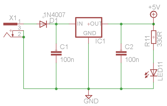
7805 IC with 5V output, polarity protection diode, and output indicator LED
The voltage measurement circuit resembles the schematic shown in Figure 4 of Chapter 22 (“Measurement Setup”), in which two ADC channels of the microcontroller are used: ADC1 measures the voltage across pins 2 and 1 of potentiometer R2, while ADC2 measures the voltage across resistor R19. This resistor is connected in series with a switchable resistor ladder and the two parallel-connected LEDs. Since the resistance of R19 is known, the current flowing through it can be calculated using Ohm’s Law. Because of the series configuration, this current is the same as the current flowing through the LEDs.
Resistors R13–R18 can be switched in or out of the circuit using the S1 microswitch. By using this switch, the total resistance can be increased or decreased, which in turn changes the current flowing through R19 and the LEDs.
The illustration also shows connector U$2, which is used for connecting the microcontroller programming interface.
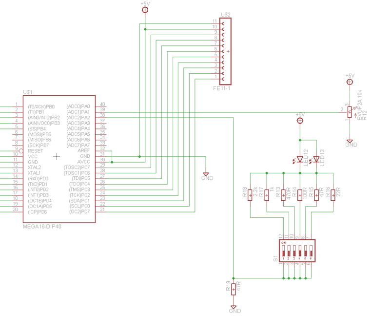
Voltage and Current Measurement Setup with Potentiometer and LEDs
LEDs named LED2 – LED6 are used to indicate measured voltage values, while LEDs labeled LED7 – LED11 display the current values. The idea is that the number of lit LEDs corresponds to the measured value. These LEDs are controlled using the Port B (PB0–PB4) and Port D (PD2–PD6) GPIO pins of the microcontroller. Connector SV1 is also used to connect the programming interface.
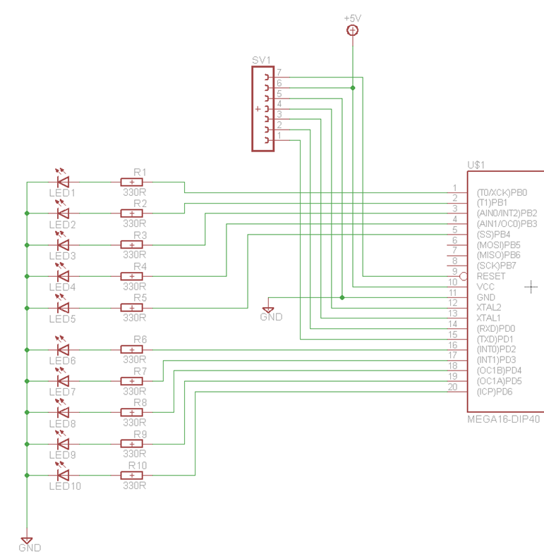
LED Wiring for Measured Value Indication
The complete circuit schematic is shown in the figure below.
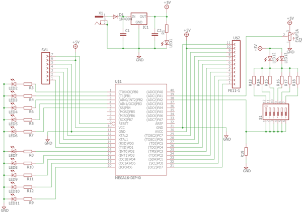
The Complete Circuit Schematic
Programming the Microcontroller
The microcontroller was programmed using the Atmel Studio development environment, which is also used throughout the CCE1 curriculum. The software written for this project consists of two main parts.
The first part includes configuration of GPIO ports and ADC channels, implementation of measurement functionality, and displaying the measured values. This part was developed based on the example code presented in Chapter 22 of the curriculum. The second part adds an extra feature: an USB connection is established with a computer using serial communication, allowing the measured voltage and current values to be sent to the computer for display. To receive and display this data on the computer, the FTDI driver must be installed, and the Hterm terminal application must be used, as described in Chapter 18 of the curriculum.
The complete source code is also included in the attached files. With the help of the comments in the code and by reviewing the related chapters of the curriculum, the program logic can be easily understood.
Bonus task beyond the curriculum
Beyond the scope of the CCE1 curriculum, the circuit schematic and printed circuit board (PCB) layout for the project were created using the Eagle software (Easily Applicable Graphical Layout Editor). The application is available for download at https://www.autodesk.com/products/fusion-360/trial-intake-flow and can be used free of charge for 30 days.
When designing the PCB, the components were arranged so that the connecting wires would cross as little as possible, and the traces could reach the component terminals efficiently. Additionally, care was taken to place the components close to each other to keep the overall board size compact. The filter capacitors were placed as close as possible to the 7805 voltage regulator. The LEDs used for visual output were arranged in two groups — one for voltage and one for current readings — positioned one below the other.
The programming interface connectors were placed right next to the corresponding pins of the ATMega16A microcontroller.
The file DIY_Multimeter.sch contains the circuit schematic, while DIY_Multimeter.brd contains the PCB layout design.
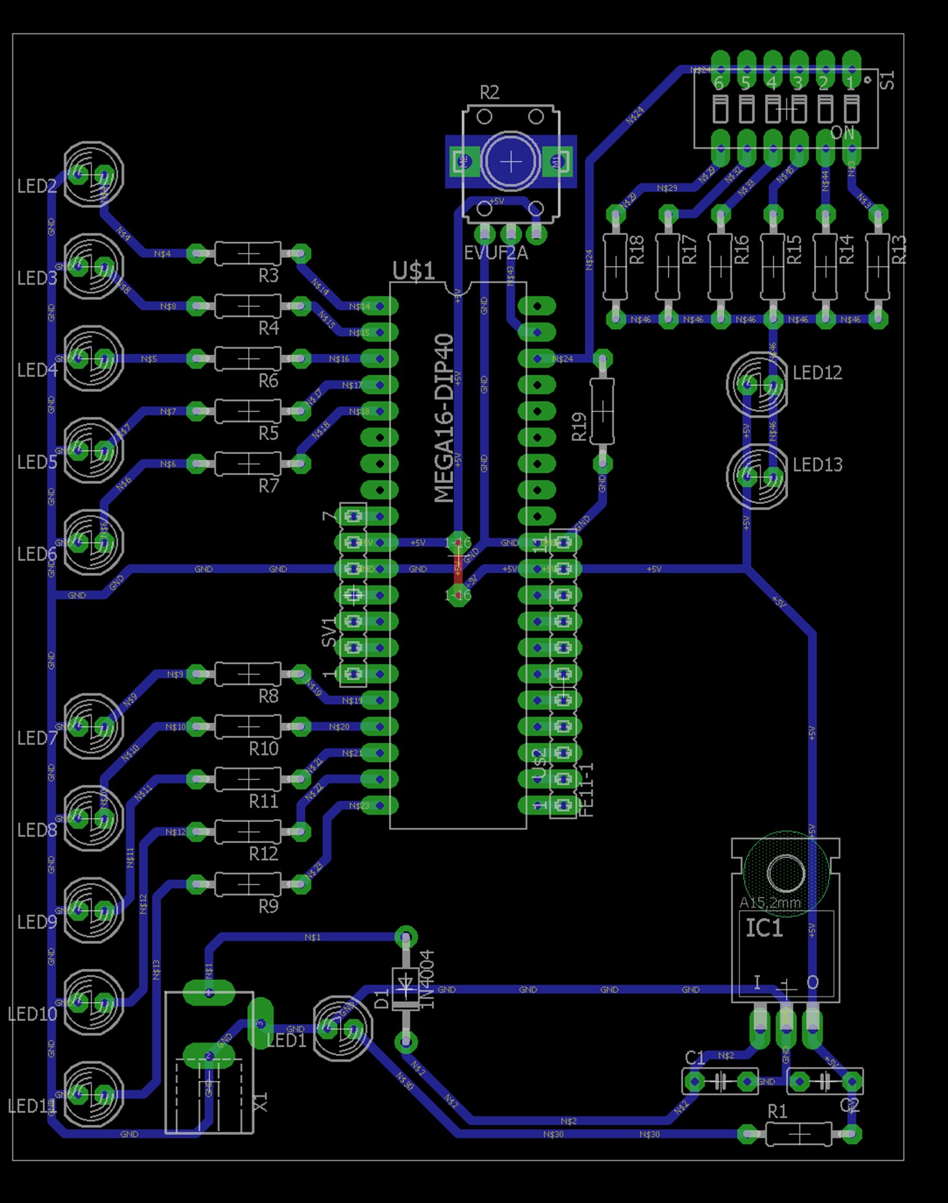
PCB layout designed by students Gergely Papp and Zoltán Imre
The folder also includes a DIY_Multimeter.pdf document containing the print-ready PCB mask. The printed circuit board was manufactured using photolithographic techniques.

PCB layout designed by students Gergely Papp and Zoltán Imre
The completed PCB with the assembled components is shown in the following images:
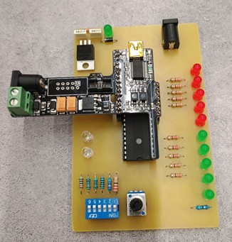
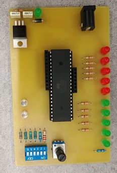
Top view of the circuit assembled by Áron Mészáros and Norbert Kraütner
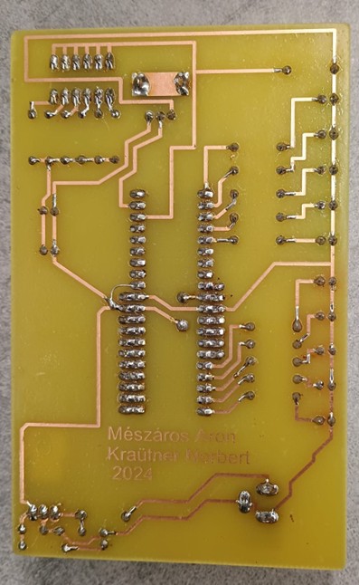
Bottom view of the circuit assembled by Áron Mészáros and Norbert Kraütner